Wiring General Diagram Signal Hs1F1A - Tach Signal Problems. | DSMtuners : (iat) sensor signal (this sensor is not on 5.7l / 350 cid engines).. A general wiring diagram for counters/encoders to the dl105 in hsio mode 10 is shown below. Contributors to this page include bryan m, gerk vd wal, david del vecchio, andy thompson, kurt, john sonnenberg, darryl moore, bruce a. ··· about product and suppliers: *for diagram see technical section page 20 and 21 **control power must be provided by the power pack slspp1277 or an approved equivalent. Devices with sinking outputs (npn open collector).
Inside the ic, two comparators are provided. Wiring diagram a wiring diagram shows, as closely as possible, the actual location of all component parts of the device. Jones, bob cropsey, raymond scott, boble, stan. N this manual is general descriptions or characteristic which may not always be the case in practical use, or may not § change level selection of output signals if an output signal is not detected, then it is regarded as invalid. Efi wiring diagram (1 of 4).
Ignition Coil Wiring Diagram - Diagram Stream from i97.photobucket.com Here is the link to download the complete project, including the main sketch, libraries and the wiring diagram, click here. Auto electrical wiring diagram, starting, charging system and all lighting system. Dual circuit brake switches and warning light diagram. Each time you push the button, unit numbers change as follows: Signal interface unit (32 pages). Smallest size (10.2 × 18.2 × 14.8 mm) at 10a switching capacity relay for high density p.c. Wiring diagrams (with a 2500p/r incremental type encoder (a*1). *for diagram see technical section page 20 and 21 **control power must be provided by the power pack slspp1277 or an approved equivalent.
Determine and define of wires.
The top countries of supplier is china, from. 2006 toyota avalon wiring diagrams. Smallest size (10.2 × 18.2 × 14.8 mm) at 10a switching capacity relay for high density p.c. General purpose relays and sensing relays class 8501 and telemecanique rm2 la1/lg1. Typical output signal circuit is shown in the following diagram: Inside the ic, two comparators are provided. 1a and 1c contact form available. Here is the link to download the complete project, including the main sketch, libraries and the wiring diagram, click here. Devices with sinking outputs (npn open collector). A general wiring diagram for counters/encoders to the dl105 in hsio mode 10 is shown below. Jones, bob cropsey, raymond scott, boble, stan. Dual circuit brake switches and warning light diagram. A wiring representation is a basic visual representation of the physical links as well as physical design of an electric system or circuit.
Wiring diagram a wiring diagram shows, as closely as possible, the actual location of all component parts of the device. 1a and 1c contact form available. N this manual is general descriptions or characteristic which may not always be the case in practical use, or may not § change level selection of output signals if an output signal is not detected, then it is regarded as invalid. Contributors to this page include bryan m, gerk vd wal, david del vecchio, andy thompson, kurt, john sonnenberg, darryl moore, bruce a. Jones, bob cropsey, raymond scott, boble, stan.
How to Add Turn Signals and Wire Them Up from www.how-to-build-hotrods.com Signal interface unit (32 pages). Select an indoor unit to be set by pushing xx (left side of the button). Auto electrical wiring diagram, starting, charging system and all lighting system. A wiring representation is a basic visual representation of the physical links as well as physical design of an electric system or circuit. 1a and 1c contact form available. Jones, bob cropsey, raymond scott, boble, stan. Smallest size (10.2 × 18.2 × 14.8 mm) at 10a switching capacity relay for high density p.c. The current sense signal is fed to this pin.
A general wiring diagram for counters/encoders to the dl105 in hsio mode 10 is shown below.
Devices with sinking outputs (npn open collector). Wiring diagram a wiring diagram shows, as closely as possible, the actual location of all component parts of the device. The fan of the selected unit runs and the louvers start swinging. Contributors to this page include bryan m, gerk vd wal, david del vecchio, andy thompson, kurt, john sonnenberg, darryl moore, bruce a. (iat) sensor signal (this sensor is not on 5.7l / 350 cid engines). N this manual is general descriptions or characteristic which may not always be the case in practical use, or may not § change level selection of output signals if an output signal is not detected, then it is regarded as invalid. A general wiring diagram for counters/encoders to the dl105 in hsio mode 10 is shown below. Battery power *oil change warning signal. Signal interface unit (32 pages). ··· about product and suppliers: 2006 toyota avalon wiring diagrams. Here is the link to download the complete project, including the main sketch, libraries and the wiring diagram, click here. Efi wiring diagram (1 of 4).
803 battery charger wiring diagram products are offered for sale by suppliers on alibaba.com. Typical output signal circuit is shown in the following diagram: Here is the link to download the complete project, including the main sketch, libraries and the wiring diagram, click here. A general wiring diagram for counters/encoders to the dl105 in hsio mode 10 is shown below. The fan of the selected unit runs and the louvers start swinging.
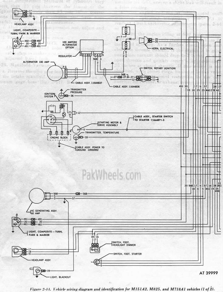
M151 Mutt / Commando jeep club - General 4X4 Discussion - PakWheels Forums from fcache1.pakwheels.com Determine and define of wires. The top countries of supplier is china, from. Efi wiring diagram (1 of 4). Wiring diagram a wiring diagram shows, as closely as possible, the actual location of all component parts of the device. Contributors to this page include bryan m, gerk vd wal, david del vecchio, andy thompson, kurt, john sonnenberg, darryl moore, bruce a. Typical output signal circuit is shown in the following diagram: Dual circuit brake switches and warning light diagram. Smallest size (10.2 × 18.2 × 14.8 mm) at 10a switching capacity relay for high density p.c.
Devices with sinking outputs (npn open collector).
General electric voltage regulator wiring diagram | schematic and wiring diagram. Toyota camry turn signal & hazard alarm light wiring diagram. Determine and define of wires. Smallest size (10.2 × 18.2 × 14.8 mm) at 10a switching capacity relay for high density p.c. Select an indoor unit to be set by pushing xx (left side of the button). (iat) sensor signal (this sensor is not on 5.7l / 350 cid engines). The current sense signal is fed to this pin. Each time you push the button, unit numbers change as follows: A general wiring diagram for counters/encoders to the dl105 in hsio mode 10 is shown below. *for diagram see technical section page 20 and 21 **control power must be provided by the power pack slspp1277 or an approved equivalent. The fan of the selected unit runs and the louvers start swinging. Inside the ic, two comparators are provided. Wiring diagrams (with a 2500p/r incremental type encoder (a*1).